


This guide explains how to use the four-channel, 70 MHz Tektronix TBS2074B for general power-electronics and electric-drives measurements. It covers the instrument setup and measurement methods that should be understood before following an experiment's connection diagram and settings.
After completing this guide, you should be able to:
Connect a ground-referenced oscilloscope without creating a short circuit or ground loop.
Compensate a passive voltage probe and configure channel coupling, probe scaling, bandwidth, inversion, and offset.
Set the vertical scale, time base, acquisition mode, record length, and edge trigger to obtain a stable waveform.
Measure frequency, duty cycle, voltage, current, ripple, ringing, and switching transitions using automatic measurements and cursors.
Create a channel-difference waveform when two nodes can be measured safely from the same reference.
Save screen images and numerical waveform data to a USB drive.
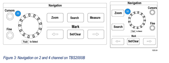
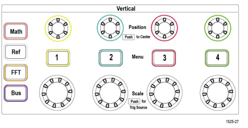
The front panel is divided into navigation, vertical, horizontal, trigger, measurement, acquisition, and save controls. Pressing a menu button opens a menu along the right side of the screen. Turn the Multipurpose knob to highlight an item and press the knob to select it.
| Control group | Purpose |
|---|---|
| Vertical | Turn channels on or off and set coupling, probe scaling, bandwidth, inversion, offset, units per division, and vertical position. |
| Horizontal | Set time per division and move the trigger point. Press Acquire to choose acquisition mode and record length. |
| Trigger | Select the trigger source, edge slope, mode, coupling, and level so repeated waveforms remain stationary. |
| Navigation | Use the Multipurpose knob for menus and cursors. Use Zoom to inspect a stopped long record. |
| Measure, Math, Cursors | Add automatic measurements, combine two channels, and make manual time or amplitude measurements. |
| Run/Stop, Single, Save | Acquire continuously, capture one event, or save an image or waveform to a USB drive. |
 Warning
The outer conductor of every channel BNC and every passive-probe ground clip is internally common and connected to protective earth through the oscilloscope power cord. Never attach a ground clip to a switching node, motor phase, or any point that is not the circuit's designated earth-referenced common. Never defeat the oscilloscope's protective-earth connection to make a floating measurement.
Connecting a passive-probe ground clip to a non-ground node can short that node to earth through the probe and oscilloscope. This can damage the probe, oscilloscope, circuit, or connected computer and can cause an arc or electric shock.
Review Safety considerations when working in power electronics and the safety instructions for every probe and accessory before beginning.
Turn OFF and de-energize the circuit before connecting, moving, or disconnecting a probe. Discharge energy-storage capacitors and verify that the node is safe.
Connect the oscilloscope to a properly grounded outlet with its three-conductor power cord. Do not use a ground-lift adapter.
Connect each probe to the oscilloscope first. Connect its reference lead to the designated circuit common before touching the probe tip to the signal.
Keep all passive-probe ground clips at the same designated common node. Use the shortest available ground lead.
Use a suitably rated differential or isolated probe when neither side of a measurement is at earth-referenced common.
Stay within the lowest voltage, current, frequency, common-mode, and measurement-category rating of every instrument and accessory in the measurement path.
Inspect the oscilloscope, power cord, probes, adapters, BNC cables, and insulation. Do not use damaged equipment.
With no test circuit connected, power on the oscilloscope and press Default Setup.
Connect a passive voltage probe to CH1. Connect its tip to the front-panel PROBE COMP 5 V terminal and its ground clip to the adjacent ground terminal.
Set the switch on the probe and the CH1 attenuation setting to the same value, normally 10X, and press Autoset.
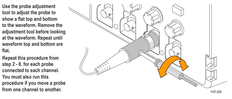
A roughly 1 kHz square wave should appear. If its top is rounded or peaked, adjust the probe compensation until the top and bottom are flat.
Repeat the procedure for every passive probe on the channel where it will be used.
Press Measure and verify that frequency is approximately 1 kHz and period is approximately 1 ms.
 Note
NoteCompensate a passive probe again whenever it is moved to another channel. Probe compensation corrects the probe's high-frequency response; it does not calibrate an external sensor or attenuator.
For every signal, identify the following information from the experiment and the equipment labels before energizing the circuit:
| Question | Why it matters |
|---|---|
| What quantity and two electrical nodes define the measurement? | Determines whether a ground-referenced passive probe is safe or whether a differential, isolated, or current probe is required. |
| What maximum and minimum values are expected? | Determines probe rating, attenuation, units per division, position, and offset. |
| What is the sensor or attenuator conversion ratio? | Determines the channel probe setting and displayed engineering units. |
| What time interval or frequency is important? | Determines time per division, record length, sample rate, and trigger source. |
| Is the goal an average waveform, ripple, a fast edge, or a rare event? | Determines bandwidth, acquisition mode, trigger mode, and whether to use averaging, peak detect, or a single acquisition. |
Press the required numbered channel button, then set each item in the channel menu:
| Setting | How to choose it |
|---|---|
| Coupling | Use DC when the average value and DC offset matter. Use AC only when intentionally removing the DC component to enlarge a small ripple. |
| Probe type and scaling | Choose Voltage or Current and enter the attenuation or conversion ratio printed on the probe, sensor, or attenuator. The physical probe setting and channel setting must agree. |
| Invert | Leave Off unless the probe or sensor polarity is opposite to the desired reference direction. |
| Offset | Use the calibrated sensor zero or another known baseline when required. Do not use offset to hide an unexplained measurement error. |
| Bandwidth | Use 20 MHz to reduce high-frequency noise in routine measurements. Use Full when true rise time, narrow spikes, or ringing is being investigated. |
| Scale and Position | Make the waveform occupy several vertical divisions without clipping. Keep the zero-reference marker visible when polarity and zero crossings matter. |
NoteA scaling error changes every displayed measurement and every saved sample. Before accepting data, compare the displayed units and expected amplitude with the probe, sensor, or attenuator label.
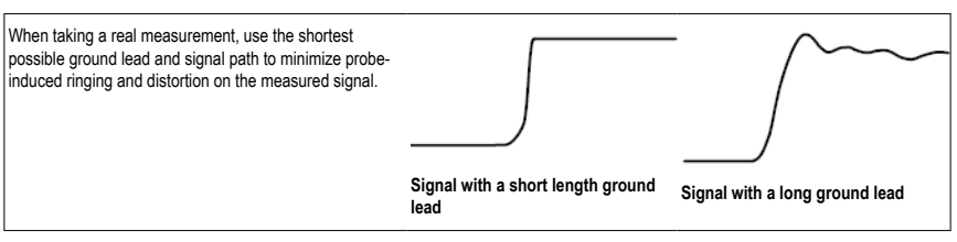
A long probe ground lead forms a larger loop inductance and can create ringing that is not present at the test point. Keep both the signal path and ground return short, especially when viewing switching edges. If a spike changes substantially when the probing loop is shortened, it was at least partly introduced by the measurement setup.
Turn on only the channels needed for the measurement. Set each channel's scale and position so the waveform is visible and not clipped.
Set the horizontal scale to show approximately 4 to 10 cycles of the repeated waveform.
Press Trigger Menu and start with:
Type: Edge.
Source: the channel with the cleanest repeated transition.
Slope: Rising or Falling, chosen for the transition of interest.
Coupling: DC.
Mode: Auto while finding the signal; Normal for a stable valid-trigger-only display.
Level: near the midpoint of the signal excursion. Press the Trigger Level knob to start at 50%, then fine-tune if needed.
Adjust time per division until the required number of cycles or the required transition fills the display.
Press Run/Stop to freeze a repetitive waveform or Single to capture one valid trigger.
| Acquisition choice | Use |
|---|---|
| Sample | Default choice for waveform shape, timing, duty cycle, and switching measurements. |
| Peak Detect | Useful for narrow spikes or intermittent ringing that Sample mode may miss. |
| High Resolution | Produces a cleaner low-frequency or average-value view, but can soften fast edges. |
| Average | Reduces uncorrelated noise on repetitive signals. Do not use it to search for intermittent events or true peak overshoot. |
Start with a record length of 20 k or 200 k points for a responsive display. Use a longer record when a long interval and fine timing detail must be captured together. After stopping the acquisition, use Zoom to inspect the stored record.
Press Measure, choose the source channel, and add only the measurements needed. The TBS2074B can display up to six automatic measurements.
| Quantity | Recommended method |
|---|---|
| Frequency, period, and duty cycle | Use Frequency, Period, and +Duty or -Duty. Verify that the trigger is stable and a complete pulse is visible. |
| Average and RMS value | Use Mean, Cycle Mean, RMS, or Cycle RMS according to whether the full record or one cycle should be evaluated. |
| Maximum, minimum, and ripple | Use Max, Min, and Peak-to-Peak. For small ripple on a large DC value, confirm the result with cursors and an appropriate bandwidth setting. |
| Rise time, fall time, and pulse width | Display the complete edge or pulse without clipping, use a stable trigger, and select the corresponding timing measurement. |
| Value at a particular instant | Use waveform cursors rather than a whole-record automatic measurement. |
NoteA warning icon beside a measurement indicates that the waveform may be clipped or the result may not yet be valid. Adjust Scale and Position until the measured portion is visible, then wait for a stable reading.
Press Cursors and choose time or amplitude cursors.
Use the Multipurpose knob to place the selected cursor. Press Fine for smaller adjustments.
For ringing frequency, place time cursors on equivalent points of adjacent cycles and use f = 1/Δt. Spanning several cycles improves accuracy.
For a switching transition, capture the waveform with Single, press Zoom, and expand the edge without changing the stored acquisition.
When measuring a zero crossing or minimum current, keep the channel's zero-reference marker visible and compare the trace with that reference.
A voltage between two non-ground nodes can sometimes be obtained by measuring each node relative to the same safe common and subtracting the channels. This method is valid only when both single-ended measurements are safe and within the probes' common-mode and voltage ratings.
Connect both probe ground clips to the same designated common node. Never place a passive-probe ground clip on either signal node.
Use the same probe type, attenuation, coupling, bandwidth, and volts per division on both channels.
Press Math, choose the first channel as Source 1, subtraction as the operator, and the second channel as Source 2.
Adjust the Math waveform's scale and position.
If edge timing matters, deskew the probes before trusting the difference waveform.
WarningChannel subtraction does not make an unsafe single-ended connection safe. Use a suitably rated differential or isolated probe when a common reference cannot be used, when the common-mode voltage is too high, or when the required bandwidth and rejection exceed the two-probe method.
Insert a USB flash drive into a USB host port. Arrange the waveforms, labels, scales, trigger point, and measurement readouts before saving.
Press Save/Recall → Action → Save Image, choose PNG, and select Save.
For repeated captures, use Save/Recall → Assign To → Screen Image, then press the front-panel File Save button.
When numerical post-processing is required, save the displayed waveform as CSV. A screen image does not contain numerical samples.
Record the channel-to-signal mapping, probe attenuation, scaling, time per division, units per division, bandwidth, and operating condition in the lab notebook.
| Symptom | Check |
|---|---|
| No waveform or a flat line | Channel enabled, probe connected, circuit energized, correct coupling selected, reasonable scale and position, and correct test point used. |
| Waveform drifts or will not lock | Edge-trigger source, slope, level, coupling, and mode. Trigger on a clean repeated transition. |
| Amplitude or units are wrong | Physical probe setting matches Probe Setup, sensor conversion is correct, channel is not unintentionally inverted, and offset is justified. |
| Unexpected high-frequency ringing | Shorten the ground lead, reduce loop area, compare 20 MHz with Full bandwidth, and compare Sample with Peak Detect. |
| Automatic measurements are unstable or flagged | Waveform is not clipped, a complete cycle is visible, trigger is stable, and the correct source is selected. |
| Difference waveform is unexpectedly large | Both channels share the same safe reference and use matching attenuation, scale, coupling, bandwidth, polarity, and deskew. |
The circuit is de-energized and every connection matches the applicable experiment diagram.
Every passive-probe ground clip is connected only to the designated common node.
The probe and accessory ratings exceed the expected voltage, current, frequency, and common-mode values.
Each channel uses the correct probe type, attenuation or conversion ratio, units, polarity, coupling, bandwidth, and offset.
The expected waveform fits on screen and the trigger source and level are reasonable.
The power-supply voltage and current limits are at their safe starting values.
TBS2000B Series Oscilloscopes User Manual (Tektronix part 077-1525-01).
TBS2000B Series Oscilloscope Installation and Safety Instructions.