In this section a simple simulation model will be built highlighting commonly used features.
Open the application and, pin the Toolbox dock on the left and Explorer dock on the right.
In Workbench, all files reside within a project. To create a new project, click the  , new project button, first icon in the Explorer dock toolbar.
In the dialog box change the file Name from UntitledProject to FirstProject. Navigate and select the desired location to save the project to using the file browser.
Clicking Accept creates a new file in the selected location with the .project extension and a folder by the same name to house the project files.
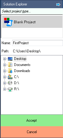
If the selected file already exists, Replace Existing? button is shown instead of Accept
Select the project by clicking on the project node in the Explorer dock.

Add a new model file to the project by clicking on the  , new file button, third icon in the Explorer dock toolbar.
 Note
NoteThe new file icon is only active when a project is selected by clicking on the project node in the Explorer dock. To avoid visual clutter and for fluid user interface, Workbench does not use any pop-up dialog boxes or right click menus. These functionalities are carried out by docks and buttons that change content dynamically based on context. For example the Delete button in the Explorer dock deleted a file, if a model or script file is selected and closes the project if project file is selected. Similarly, Explorer dock shows project structure as well as acts as a file browser, all based on the context.
Select Model File from the file type options and change Name from UntitledFile to FirstModel. Leave the file path at default value.
 Note
NoteThe newly created file can be located anywhere. It is recommended though that the file be located in the folder that was created automatically (same name as project) when a new project was created or, in subfolders within it. This allows for easier protability between devices. If files were added outside this folder, when they are moved to another device with different folder paths, they need to be maually removed and added again to the project.
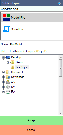
Clicking Accept will add the model file to the project and the blank model is displayed in the dock. If the model is closed at anytime, it can be brought back up clicking on the model node in the Explorer.
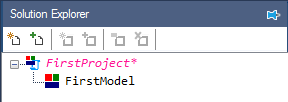
All unsaved files are highlighted in color with * following the node in Explorer as seen above. In the following steps a simple sine wave is simulated and plotted.
Bring the Toolbox dock to the front if hidden, by clicking on the Toolbox tab on the left. Navigate to Signal Sources class in the dropdown menu. Select and drag the Sine tool and drop it on the model file.
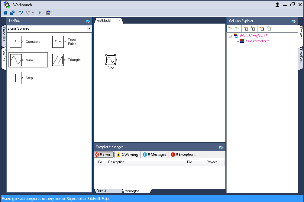
Most design errors and possible mistakes are caught instantaneously by the Workbench compilation engine.
In this case, there is one warning reported as indictated by the Compiler Messages toolbar in the bottom dock.
Click on the  button to see the warning thrown.

Clicking on the message leads to the source of the message. For information regarding the nature of the message, common causes and how to fix them visit: Decoding Compiler codes
Navigate to Display class in the Toolbox dropdown menu. Select and drag the Mag-Time Scope tool and drop it on the model file.
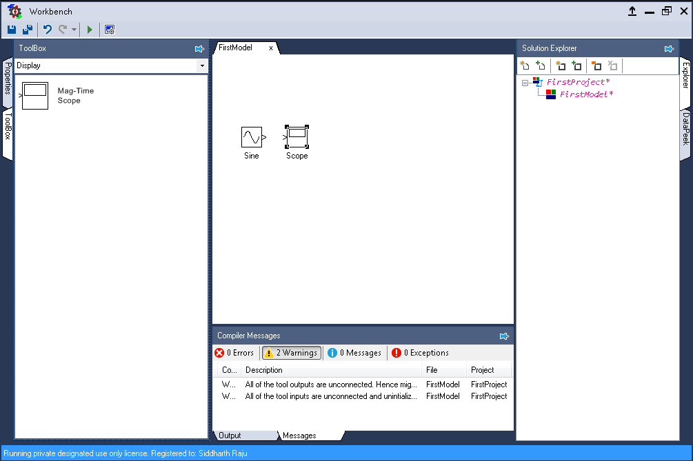
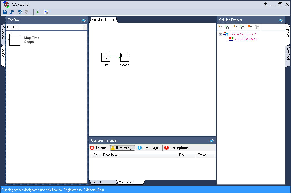
There are currently two warnings displayed, one for each unconneted tool input or output. Click on the output port of Sine block in the model and while the mouse button is pressed down, move the cursor to the input port of Scope block and release the button. If the routing is successful, a green link appears that connect the two tools together. If the mouse button was released prior to reaching the input port, a red unfished link appears. This can be fixed by extending the link from where it was left off or deleting and attempting again. The various routing methods as discussed in next tutorial.
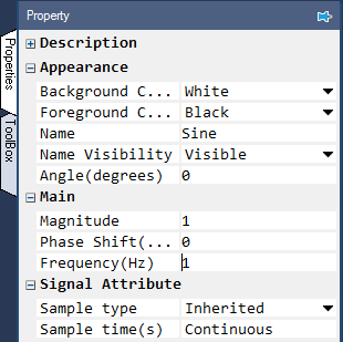
The magnitude and frequency of Sine block can be modified by changing it properties. To do this, click on the Properties tab, which is above the Toolbox tab on the left. This dock displays the properties of tool, model, project and code element based on which has been currently selected. To look at the property of Sine block, click on that tool.
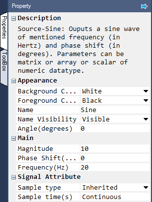
Click on the  icon in the
 Description field to read about the tool description.
More details regarding the tools and their properties can be found here: List of model tools.
Change the Magnitude property from 1, to 10 and the Frequency (Hz) from 1, to 20.
Clicking on the  at this point will throw the following error in the output dock in the bottom:

In this case a project file consists of just a single model file. But in most cases, it usually consists of multiple model and script files within it. So, the project file must be told which of those files needs to be run at which point. To do this, double click on the project node, FirstProject in the Explorer dock. This will load the project properties in the Properties dock. In the Start model/Function filed set the name of the model file FirstModel.
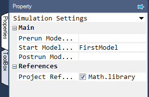
 Note
NoteUnlike most programming languages the whole Workbench environment is case insensitive. In the above case FirstModel could have been typed as fIRSTMoDel or any other possible combination. As long as the exact content matches it should be fine. On the other hand, if the file name was typed wrong, for instance missing a character or has a wrong character, a squiglly line would appear under the entered text indicating an error and this error will be logged in the Compiler Messages dock.
The other options in the project property namely, Prerun Model/Function and Postrun model/function are generally used to call script file when variables need to initialized that are used by the model before running the model and processing the data generated by the model after its run respectively.
Click the  button to run the simulation.
Once the project has run successfully the following message is shown in the output window:

Double click on the Scope in the model file to inspect the resultant plot.
Click the  button, second button in the scope's toolbar on the top, to auto-focus the result.
This could also be achieved by double clicking on the scope where the data has been plotted.
This is plot of a 20 Hz sine wave for 10s, with X-axis representing time and Y-axis magnitude. Zoom in the result to a small time interval to get a better view of the result. To do this, click the  ,
fifth button in the scope tool bar, and hold the mouse button down at say time t = 2 s and drag the mouse while button is pressed down, to t = 2.5 s and release the mouse (the time selection needn't be exact). This should show the following plot or something similar.
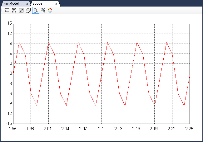
The plot is not visually smooth because the default model solver step time Ts = 0.01 s is not small enough too large for this scenario. This can be fixed by changing the model step time from 0.01 to 0.001. To do this, go back to the model file by clicking on the FirstModel tab in the center dock. Double click anywhere to populate the Properties dock with model's proerties. Change the Step time(s) property to 0.001. While at it, change the Run time(s) property to 5.
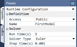
Run the simulation again by clicking  .
Go back to the scope results and click
  to auto-focus the result.
The results will be much smoother due to increased samples.
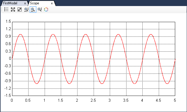
Click the  in the top dock to save both the model and project file.