


In this experiment, four-quadrant operation of a DC motor is simulated and run in real time. The speed and current control model developed in the previous experiment is used to emulate the four regions of operation.
Consider the elevator system shown in the figure below. It consists of a carriage, a counterweight, and a pulley driven by a DC motor. The counterweight is usually set to around 50% of the fully loaded weight of the carriage to maximize overall efficiency.
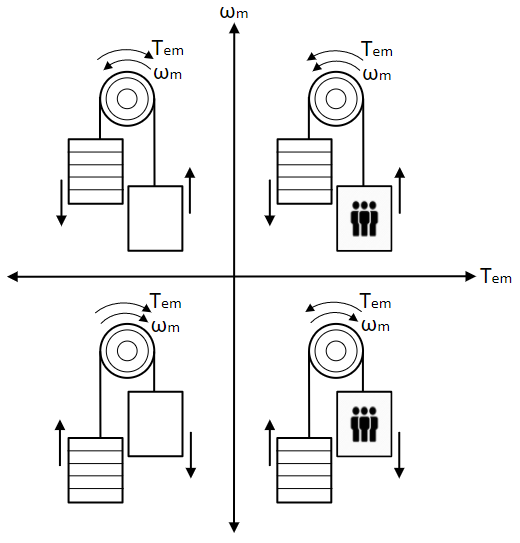
This system goes through all the 4 quadrants of operation, namely:
Forward motoring: ωm is positive and Tem is positive.
Forward regeneration/braking/generation: ωm is positive and Tem is negative.
Reverse motoring: ωm is negative and Tem is negative.
Reverse regeneration/braking/generation: ωm is negative and Tem is positive.
Forward motoring occurs when the carriage is loaded more than the counterweight and needs to be pulled up. In this case, the DC motor must produce torque in the direction of rotation to compensate for the lighter counterweight. Forward regeneration occurs when the carriage is loaded less than the counterweight and needs to be pulled up. In this case, the DC motor must produce torque against the direction of rotation to prevent the carriage from being drawn up too quickly by the heavier counterweight. Reverse motoring occurs when the carriage is loaded less than the counterweight and needs to be pulled down. In this case, the DC motor must produce torque in the direction of rotation to compensate for the lower weight of the carriage. Reverse regeneration occurs when the carriage is loaded more than the counterweight and needs to be pulled down. In this case, the DC motor must produce torque against the direction of rotation to prevent the carriage from being lowered too quickly due to its greater weight.
In motoring mode, power is drawn from the source and delivered to the motor; in regeneration mode, power is returned from the motor to the source.
Forward motoring:
Open the speed control simulation model designed in the previous experiment.
Set the reference speed using Step, with Final value equal to 100 and Step time equal to 1.
Set the load torque using Step1, with Final value equal to 0.2 and Step time equal to 7.
From the Toolbox, drag and drop the Multiplier Divider tool from the Math Block tool class. Use this multiplier to multiply the motor terminal voltage by the motor current. Add a Scope from the Toolbox to observe the result of the multiplication.
Similarly, add a multiplier to multiply the motor output torque by the motor speed, and add a scope to observe the result. The motor torque can be obtained by scaling the motor current by kt using a Gain block.
Add a scope to observe the motor output torque.
Run the simulation model and observe the current, speed, output torque, input power, and output power.
Forward regeneration: In the model, change the Final value of the load torque step to -0.2 and rerun the model. Observe all the results as before.
Reverse motoring: In the model, change the Final value of the reference speed step to -100 and rerun the model. Observe all the results as before.
Reverse regeneration: In the model, change the Final value of the load torque step to 0.2 and rerun the model. Observe all the results as before.
In the previous section, the motor's four-quadrant operation was simulated. In this section, the same system is run in real time.
Open the real-time speed-control model designed in the previous experiment.
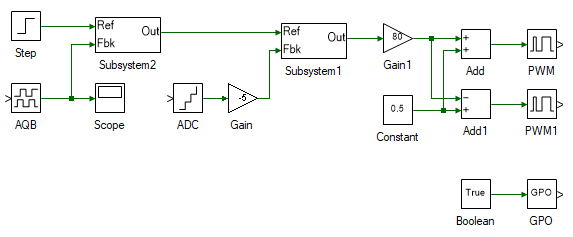
Open model properties and set the Step time to 0.0001 and Run time to 10.
Previously, this system was run in real time without any load. In this experiment, a torque load is emulated by means of another DC motor coupled to the speed-controlled DC motor. The second motor is run in current-control mode, which in turn is torque-controlled since torque is simply kt times the motor current. To do this, select, copy, and paste everything to the right of the speed PI controller, as shown:
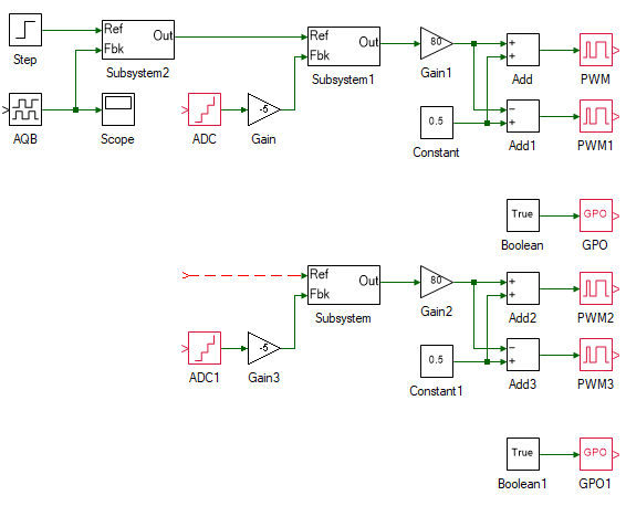
The newly pasted system is the current-controlled DC motor, which will be connected to Inverter 2. The PWM and ADC settings need to be changed to reflect this.
Change the properties of each tool in the newly pasted system to the values listed in the table below.
| Tool name | Property field | Property value | Comments |
|---|---|---|---|
| ADC1 | Channel | 5 | Second motor's current. |
| Gain3 | Gain | 5 | Scaling to convert ADC signal to actual current. The scaling value is given within the ADC property. |
| PWM2 | Channel | 4 | Inverter 2's A-phase leg. |
| PWM3 | Channel | 5 | Inverter 2's B-phase leg. |
| GPO1 | Channel | 2 | Pull inverter 2 out of reset. |
Add a step tool and connect it to the reference input of the PI controller subsystem of the recently pasted system. This step is the reference current. As in the simulation, the load torque of the motor is to be stepped to 0.2 Nm. This can be achieved by proportionately stepping the current by 0.2/kt, where kt must be substituted with the value obtained from DC motor characterization experiment. Thus, set the Final value of the step tool to 0.2/kt (substitute value for kt) and the Step time is set to 7.
Add a scope to observe the output current of the motor. In the scope properties, enable data logging.
Connect the motor (the one without the encoder) to Inverter 1 (the color of each motor terminal must match that of the corresponding inverter terminal). Connect the generator (the one with the encoder) to Inverter 2 (once again, the color of each motor terminal must match that of the corresponding inverter terminal).
Connect the three-inverter module to the DC power supply. Connect the three-inverter to the computer via USB. Connect the generator speed feedback to the three-inverter's Encoder 1 DSUB connector in the back panel.
Turn ON the DC power supply and set the voltage to 40 V.
Ensure that the  button on the top dock is pressed to enable real-time mode. Click the run button.
Observe the speed and current results in the scope. Click  to focus the results. After about 10 s, stop data logging by clicking
  .
.
Turn OFF the DC power supply.
As in the simulation, alternate the signs of the reference speed and current, and obtain results for all modes of operation.
Turn OFF the DC power supply and disconnect all the connections including the USB.
This concludes the experiment on DC motor four-quadrant operation. In the following experiments, AC motors will be explored.
Attach plots of Ia or Tem, and ωm, from the simulation and real-time runs under all modes of operation.
What was the input power and output power for all four modes, after load torque was applied? Is input power greater or less than output power? Explain the results.
Given an elevator with a counterweight of 250 N, a pulley with a diameter of 0.5 m, and a motor with a maximum current of 100 A and a torque constant of 10 N·m/A, what is the maximum capacity of the carriage?