In this experiment, permanent magnet AC motor's load-angle variation as function of electromagnetic torque is characterized. This is followed by closed loop speed control using hysteretic current control.
One of the major disadvantages of DC motors is the requirement of commutator brushes that constantly wear-out. This requirement is overcome in PMAC motors by means of sinusoidally distributed winding, which under balanced 3Φ sinusoidal stator currents, creates a rotating magnetic field. A simplified radial cut-out of a 2-pole PMAC machine is shown below, showing the sinusoidal stator conductor density distribution.
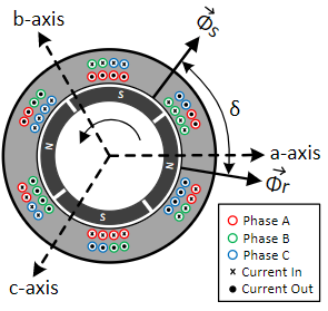
Stator flux space-vector Φs due to currents in the stator windings interacts with the rotor flux Φr due to permanent magnets mounted on the rotor, creating electromagnetic torque Tem, given by:
Tem ∝ Φs × Φr × sin(δ) ∝ Is × Φr × sin(δ)(1)
where, δ is the load-angle, which is the angle between the stator flux and the rotor flux space-vectors.
The stator current space vector Is is given by the Clarke transform:
Is = Ia + Ib × ej2π/3 + Ic × ej4π/3(2)
For a constant stator current magnitude, the variation of electromagnetic torque as function of load-angle (Eqn. 1) is as shown below:
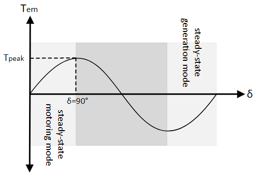
Maximum Tem occurs when the stator current induced flux is at 90° to rotor flux. If the load torque under steady-state was to exceed this, the motor goes into unstable operating condition and rapidly comes to a stand-still.
To generate a constant steady-state torque to keep the rotor spinning under constant load, the stator current induced flux is maintained at an angle between 0 and π/2 with respect to the rotor flux. This is achieved by exciting the stator windings with 3Φ balanced sinusoidal voltages, leading to a rotating stator flux space-vector whose rotational speed is given by:
ωsync = 2P × ωs = 2P × 2πf(3)
where, ωsync is the synchronous rotor flux speed which equals the mechanical rotor speed ωmech at steady-state, f is the frequency of the terminal voltage and P is the number to rotor pole pairs.
If the load torque were to be greater than the maximum generatable electromagnetic torque, identified in the above figure, the load-angle δ will increase past π/2, at which point the motor enters unstable operating point where the generated torque would keep decreasing leading to further increase in load-angle which in turn leads to further reduction in electromagnetic torque and this cycle continues until the motor stalls.
Open loop speed control
The per-phase equivalent circuit of a PMAC motor under steady-state condition is shown below:
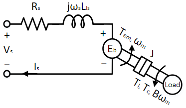
The backemf Eb is proportional to the rotational speed:
Eb = ke × ωmech(4)
From Eqn. 3, the speed of PMAC motors is solely dependent on the input voltage frequency. The magnitude of the applied voltage controls the maximum electromagnetic torque. At motor start, rated motor voltage cannot be directly applied because the back emf is zero and hence would lead to high inrush currents which could potentially damage the motor. The same principle extends to low speeds as well, where there wouldn't be sufficient back-emf build up to limit the current due to the applied voltage. At high speeds, applying less than the required voltage would leads to insufficient stator current, in turn insufficient peak electromagnetic torque which is lower than load torque, which will bring the motor to stall as explained earlier. This leads to a high short circuit-current (due to zero back-emf). Hence to avoid either extremes, the V/f (V-by-f) control is used for open loop speed control where, the applied stator voltage magnitude Va is controlled proportional to the applied stator voltage frequency fa. This is given by:
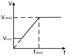
Va = Vratedfrated × fa(5)
This control scheme is summarized in the following figure. As seen, under nominal operating conditions, the applied voltage and the frequency are proportional to one another. At speeds higher than the rated, the voltage is limited to rated voltage Vrated. This could be either due to limitation in the available voltage or simply to avoid damaging the motor winding. At very low speed, a constant voltage Vmin is applied to overcome the high initial static friction as well as drop across the stator winding resistance.
Closed loop speed control
Unlike DC motors covered in previous experiments, the PMAC motor's speed does not change with load torque since it is solely determined by the applied stator voltage frequency. But this does not mean the motor is operating at optimal efficiency. The optimal operating point is where the load-angle δ is maintained at π/2 irrespective of the desired speed and load torque conditions. This ensures that the desired electromagnetic, equal to load torque at steady-state, is generated for the least stator current. This ensures lower loses and hence higher efficiency.
To achieve this, similar to DC motor closed loop speed control, an inner current loop control is added to the outer speed loop control. In the case of DC motor, the output of the outer speed loop controller was reference rotor current. In case of PMAC motor control, the output of the same is the magnitude of the desired 3Φ stator current, Im. The angle of the stator current space vector is maintained at π/2 greater than the rotor flux space vector angle Φr, as per the above discussion. The 3Φ reference current is given by:
Ia,ref = Im × sin(Φr + π2)(6)
Ib,ref = Im × sin(Φr + π2 - 2π3)(7)
Ic,ref = Im × sin(Φr + π2 - 4π3)(8)
where, Φr = P2∫ ωmech dt.
The desired reference current is generated using Hysteresis-control. In this method, if the difference between the actual current and reference current of a phase is less than a certain threshold, the corresponding motor phase terminal is connected to the positive DC bus, by turning on the top switch of the corresponding inverter leg, to increase the phase current. Similarly, if the difference between the actual current and reference current of a phase is greater than a certain threshold, the corresponding motor phase terminal is connected to the negative DC bus, by turning on the bottom switch of the corresponding inverter leg, to reduce the phase current. This method is summarized in the figure below:
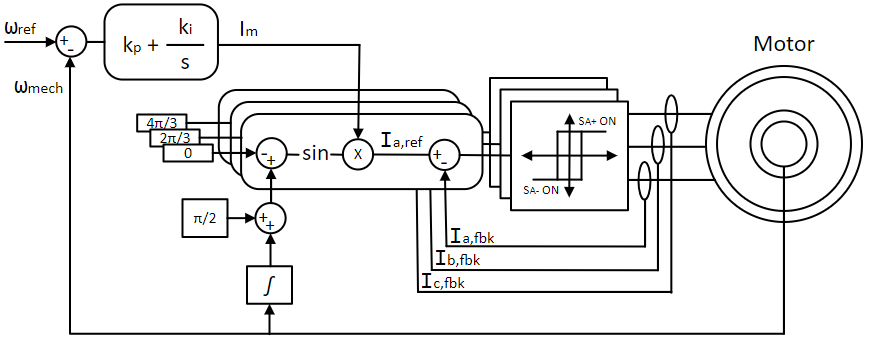
In the following section, the PMAC motor will be run at different speeds and load torque condition using the V/f control and the load-angle variation will be characterized. This will be followed by running the motor in closed speed control using hysteresis current control.
Assemble the PMAC motor-DC motor set as shown below:

DC Generator (one with A-quad-B encoder mounted on its back).
PMAC Motor.
Oldham coupler. Tighten if loose using M2.5 hex wrench.
Oldham coupling disk. Attach it to the motor and generator coupling.
Safety enclosure. The coupling unit resides inside the safety enclosure.
M4 hex socket-head screws - x8.
M2.5 hex wrench - Tighten the motor and generator onto the safety enclosure.
2048-line A-quad-B encoder - Attach the encoder cable to the A-quad-B encoder.
The wiring color code followed is:
DC (Inverter input):
DC +ve - ● (Red)
Ground - ● (Green)
DC -ve - ● (Black)AC (Inverter output):
Phase A - ● (Black)
Phase B - ● (Red)
Phase C - ● (Blue)
The inverter output terminals are located on the front panel of the three-inverter module. Connect the PMAC motor terminals to the Inverter 1 terminals such that the color of both these terminals matches one another. Connect the DC generator -ve (black terminal) to Inverter 2 A phase (black terminal) and DC generator +ve (red terminal) to Inverter 2 B phase (red terminal). The DC generator might have a third cable with green terminal. This is the ground wire and must be left unconnected.
 Warning
Ensure that the DC power supply is turned off before making the connections. If the DC power supply does not have a dedictated ground terminal, that connection can be left floating. If present, it is strongly recommended that it be connected to the three-inverter module's ground terminal to mitigate any electrical hazard.
Connect the three-inverter to the computer via USB. Connect the generator speed feedback to the three-inverter's Encoder 1 DSUB connector in the back panel.
Open Workbench and pin the Explorer and Properties dock.
Navigate to and open the PMVbyF project file in Experiment6\PMLoadAngle folder usually in the following location: C:\Program Files (x86)\Sciamble\WorkBench v1\Examples\CUSPLab\BasicDrives.
Expand the project and open the RotorInit model file shown below:
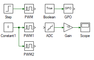
The incremental encoder used does not output the actual absolute position of the rotor. Rather it outputs a pulse when the rotor turns by a certain angle. Since the initial rotor position cannot be known using the incremental encoder, it is forcefully initialized to a pre-determined position. This is achieved by briefly connecting the phase-A winding to Vdc and the phase-B and C winding to 0, as done so in RotorInit model file. This ensures that the initial rotor magnetic flux axis is aligned along the stator phase-A winding axis.
Open project properties by double clicking on the project node in Explorer and set the Start model/Function to RotorInit.
Turn ON the DC power supply and set the voltage to 40 V.
Ensure that  button on the top dock, to transition to real-time mode, is pressed. Click the
  button.
After about 5s, click the  button to stop the model.
Open the VbyF model file within the project in the Explorer dock. The model file is shown below:
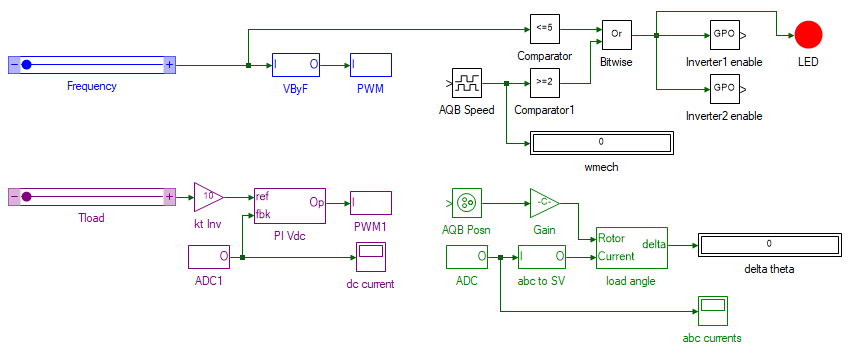
The tools highlighted in purple is the closed loop current PI-controller, which controls the load torque applied by the DC generator coupled to the PMAC motor. This is same as the method employed in previous experiments to emulate a load torque. The tools highlighted in green computes the difference between the rotor flux position, obtained from the position encoder, and the stator current space vector Is as per Eqn. 2. The computed difference is conditioned to be between ±180°. During the running of this experiment, if the applied load torque (Tload slider) exceeds the peak PMAC motors electromagnetic torque, the rotor stalls and this could lead to high short circuit currents that could potentially damage the motor. This is avoided by the logic implemented by the tools in black, where the inverter is disabled if both the rotor speed is less than 2 rads/s and the applied stator frequency is greater than 5 Hz.
Finally, the tools highlighted in blue generate the PWM signals for the inverter connected to PMAC motor. The frequency of applied terminal voltage is controlled by the slider. The internal implementation of the VByF subsystem is shown below. As can be seen, the frequency f is scaled by the V/f factor which equals the back-emf constant ke of 0.02 V/rad/s. Within the saturation block, the maximum phase voltage is limited to 20 V, within motor rated voltage, and the minimum voltage is limited to 4 V, required to overcome the initial static friction.
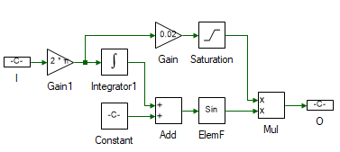
Open project properties by double clicking on the project node in Explorer and set the Start model/Function to VbyF.
Ensure that  button on the top dock, to transition to real-time mode, is pressed. Click the
  button.
Move the Frequency slider gradually to 30 Hz.
Increment the load applied by increasing the Tload slider in steps 0.005 Nm. At each step make note of the load-angle in the deltaTheta display and the rotor speed ωmech. When load torque exceeds the maximum electromagnetic torque synthesizable for the applied terminal voltage, the motor stalls. In which case, reduce the load torque back to 0 Nm and the frequency back to 0 Hz. Then gradually increase the frequency to 30 Hz. Now decrease the load torque in steps of -0.005 Nm, and record the load-angle and rotor speed.
| Tl (Nm) | ωmech (rads/s at f=30Hz) | δ (° at f=30Hz) | ωmech (rads/s at f=40Hz) | δ (° at f=40Hz) | ωmech (rads/s at f=50Hz) | δ (° at f=50Hz) |
|---|---|---|---|---|---|---|
-0.12 |
||||||
⋮ |
||||||
0.0 |
||||||
⋮ |
||||||
0.12 |
 Note
NoteThe maximum steady-state load-angle can be is 90°. If the display gives a value above this, ignore the reading. This happens because the current space vector's angle is computed from current measured from the ADCs connected to the current sensors. These generally have an offset which causes the measured value to be slightly different from the actual value. This causes the computed space vector position to be slightly different from the actual current space vector position.
Reduce the load torque back to 0 Nm and the frequency back to 0 Hz. Repeat the previous two steps for 40 Hz and 50 Hz.
Click the  button to stop the model.
This is the torque - load-angle characteristic of the PMAC motor. In the next part of the experiment, a closed loop speed controller with hysteresis inner loop current controller is implemented to maintain the speed constant and the load-angle at π/2 for maximum efficiency. The speed controller design is similar to that of DC motor speed controller since the per-phase equivalent circuit is the same. The model is run in simulation on a mathematical model of a PMAC motor and the same is run in real-time and the results are observed. The details of the motor model design are part of the advanced electric drives lab and is not discussed here. For further reading refer to: Vector control of PMSM.
Open Workbench and pin the Explorer and Properties dock.
Navigate to and open the PMHysteresisControl project file in Experiment6\PMCurrentControl folder usually in the following location: C:\Program Files (x86)\Sciamble\WorkBench v1\Examples\CUSPLab\BasicDrives.
Expand the project and open the Hysteresis model file shown below:
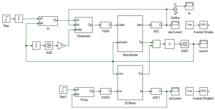
The top section of the model consists of the PMAC motor model, preceded by the inner hysteresis current controller and that is preceded by the outer speed PI-controller. The bottom section of the model contains the DC generator model, with a PI-controller to regulate the current, in turn controlling the load torque. The motor reference speed is gradually increased from 0 to 150 rads/s at time 1 s. At time 3 s, the DC generator reference current is stepped to 0.2 A to generate a load torque of 0.04 Nm.
Ensure that  is NOT pressed. Click the
  button.
Observe the PMAC motor speed and stator current response.
Open project properties by double clicking on the project node in Explorer and set the Start model/Function to RotorInit.
Turn ON the DC power supply and set the voltage to 26 V. Hysteresis control adjusts the output current by rapidly switching between the DC voltage levels. Lower the difference between these levels, lesser the rate of switching.
 Note
NoteDC power supply voltage is to be set at 26V, not 40V.
Ensure that  button is pressed. Click the
  button.
After about 5s, click the  button to stop the model.
Reset the Start model/Function to Hysteresis.
Ensure that  button is pressed. Click the
  button.
After about 10 s, click the  button to stop the model.
Observe the motor speed.
This concludes the experiment on torque angle characterization, open loop V/f and closed loop Hysteresis speed control of PMAC motor. In most real-world application, the vector control of PMAC is employed instead of the Hysteresis control covered in this experiment, due to high harmonic content in the stator current in case of the latter. This increased harmonic causes increased torque pulsations, increased audible noise and vibrations, increased thermal losses etc. In addition, hysteresis control requires the power electronics to handle very high switching frequency which varies inversely with motor leakage inductance. Thus, it becomes especially unsuitable for motors with very low time constants such as the one used here. The vector control of PMAC motor is dealt in the advanced drives lab and for further reading refer to: Vector control of PMSM.
Plot the result of Tload (y-axis) as function of load-angle δ (x-axis) for 30, 40 and 50 Hz, under open loop V/f control. Mark the region where PMAC is in motoring mode and where it is in generation mode.
What was the load-angle for all three frequencies at 0 Nm load torque? If it is non-zero explain why it is so.
At what load torque does load-angle become 0? What is the PMAC motor's electromagnetic torque at this point?
Attach plot of ωmech under open loop speed control for all the different frequencies.
What is the steady state load-angle δ under closed loop hysteresis-current control used in this experiment? Explain the reason of the value chosen.
Attach plot of ωmech under closed loop speed control for a step change in reference speed and load-torque, from both simulation and real-time.
Attach plot of PMAC motor 3Φ stator currents under closed loop speed control, from simulation. Zoom in at time interval between 2.95 - 3.05 s.
What would happen if a PMAC motor is directly connected to its rated voltage at rated frequency starting from zero steady state condition?